How to mirror parts.
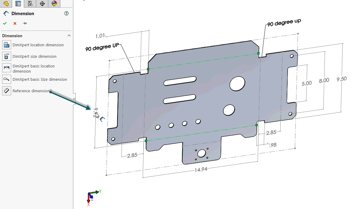
Dimensioning sheet metal parts solidworks.
In this tutorial video we will learn how to sketch sheet metal drawings in solidworks with the help of sheet metal tools.
Sheet metal options vary depending on whether you are working with a part assembly or drawing.
The sheet metal tool allows you to quickly create sheet metal part designs using a simple design process all helping to save time and development costs.
Please subscribe our channel for mo.
Select your sketch in the feature tree then in the command manager select the base flange function from the sheet metal tab.
How to model complex sheet metal parts in solidworks.
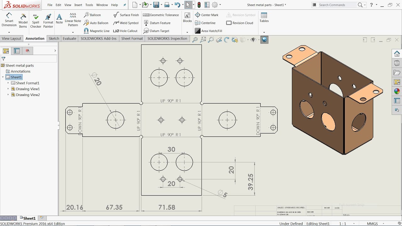
Drawings of sheet metal parts can also contain views of the bent sheet metal part.
You can create dxf files of sheet metal flat patterns without creating a drawing.
Sheet metal parts are generally used as enclosures for components or to provide support to other components.
You can create a configuration in a sheet metal part that shows the flattened part.
Add a dimension to set the depth of your profile in this case 10mm.
You can design a sheet metal part on its own without any references to the parts it will enclose you can design the part in the context of an assembly that contains the enclosed components or you can design the part within another part document in a multibody environment.
Drawings of sheet metal parts can also contain views of the bent sheet metal part.
Sheet metal gauge bend table.
Sheet metal gauge bend tables store properties for a designated material.
Sheet metal properties properties specific to sheet metal parts are calculated and displayed in the cut list properties dialog box.
Check override default parameters if you wish to adjust.
Click make drawing from part assembly standard toolbar and click ok to open the drawing sheet.
Select a format or click ok to use the default format.
To create a drawing of a flat pattern.
Creating drawings of flat patterns.
Open the sheet metal part for which you want to add a drawing.
Sketch and use smart dimension to give a dimension to the design.
Creating sheet metal flat pattern configurations.